 The installation was carried out by Genvex's UK distributors Total Home Environment Limited (THE) and was completed in five days using three people for the first day to remove the old system and one person for four days; we had a particularly competent installation engineer.
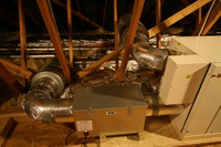
THE returned to commission the system and fine tune the inlet and exhaust air flows in each of the rooms for optimum operation. The pictures show the completed installation. You may click on the photos to see a larger image.
We are very pleased with the end result.
In the photo on the le ft, the large white box is the ventilation and heat recovery unit. The box also contains the air sourced heat pump. The small white box in front of the large box contains the microprocessor and electronics. The silvery rectangular box at the front is the optional electrostatic filter. The large 'drums' in line with the pipes are the silencers which eliminate noise transmission into the bungalow.
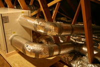
Here we have a better view of the electrostatic filter which filters out pollen and potentially harmful viruses. Note the kettle lead powering it with the light being on. All ducting in our installation is with rigid galvanized steel tubing with a double wrap of insulation on all pipes that is equivalent to 100 mm of fibreglass. The lower pipe is for the supply of air to living rooms and bedrooms. The upper pipe is for the extracted air taken from the kitchen, utility room and bathrooms. The electrostatic filter removes pollen and so helps asthma and hay fever sufferers.
 At the other end of the unit is the inlet air pipe at the top that is ducted from outside. The stale moist exhaust air is blown out through the lower pipe.
Both of these pipes are 160 mm in diameter and are insulated. In winter, when the air sourced heat pump is running the air blown outside can be -12C when the outside air temperature is 5C.
Conversely, in summer when the heat pump is operating in reverse, the exhaust air can be up to 45C when the outside air temperature is 25C.
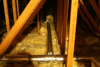
Rig id ducting has been used throughout the installation. This has a considerable advantage over flexible ducting as it results in: superior air flow as there is less air resistance; the ability to carry a greater volume of air for a specific pipe diameter; significantly lower noise; and no susceptibility to flattening of the pipes. Note how very carefully the engineer installed the ducting and all the units. The high level of pipe insulation minimizes heat loss when heating and heat gain when cooling.
 This shows the Optima 300 controller operating in the winter with the air sourced heat pump operating. Note here that "Fresh Air" is brought in from outside at 9.2C, goes through the cross flow heat exchanger and heat pump and is blown to the rooms at 43C.
Next stale moist air is extracted at 17.3C and again goes through the heat exchanger and heat pump to be blown outside at 1.6C. Using the heat pump in winter allows us to turn our storage heaters off early.
The heat pump uses around 250W, yet it provides the equivalent of 1KW of heat energy. The controller is fully programmable, and I will create a separate web page on the controller.
In summer, the heat p ump works in reverse and cools the incoming air while reducing the humidity to make the environment more comfortable.
With the recent hot weather, here are details of the heat pump providing cooling. Note here that "Fresh Air" is brought in from outside at 23.9C, goes through the cross flow heat exchanger and heat pump and is blown to the rooms at 11.4C.
Next, stale moist air is extracted at 27.3C and again goes through the heat exchanger and heat pump to be blown outside at 44.4C.
Now that we have the air conditioning units working, we go not use the Optima for summer cooling, but we sometimes use it to warm the air in very cold weather.
While the installation c an be used just as it was left by the installation team very satisfactorily, it does provide the enthusiast the opportunity to play with it. Sophisticated settings can be optimized very easily using the buttons on the controller above.
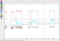
But, the unit has a USB interface that can be used to easily set up the controller. Additionally, it has an SD card and the operational data can be viewed using the data logger program. Let us just explore what has been happening to the unit. These graphs are of the heat pump operating in heating mode. The red line is the supply air being blown into the rooms; notice that when the heat pump is running, the supply air is around 40C; with the heat pump not running, it is 13C.

